 Voltage selection device
TU U27.1-32431587-021:2021
Purpose
The voltage tapping device (UON) is designed to tap voltage from coupling capacitors on existing and planned high-voltage lines with a rated voltage from 35 to 750 kV inclusive, alternating current with a frequency of 50 and 60 Hz, as well as for transmitting measurement information signals to automatic reclosing devices (AR ) and synchronization devices.
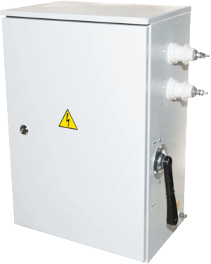
Design
The design of the UON is a technical stainless steel case with fastening and protection elements. The case has an additional paintwork. Elements of the UON circuit are placed on a frame attached to the rear wall. UON design provides for grounding of the lower lining of the coupling capacitor, which allows connection to the PET without disconnecting the voltage tap from the coupling capacitor. UON is designed to work with coupling capacitors of the CM type.
Degree of protection: IP 54.
The group of operating conditions in terms of the impact of mechanical factors is M1 according to GOST 17516-92.
The voltage selection device is designed to operate in weather and climatic conditions corresponding to GOST 15543.1-89 and GOST 15150-69 category II (U1 and UHL1).
Overall and mounting dimensions of UON
Installation method: hinged execution.
Overall dimensions: 730*485*280.
The mass of the product is not more than 25 kg.
A warranty period is set for voltage tapping devices - 6 months from the date of putting the device into operation, but not more than 1.5 years from the date of shipment.
By individual agreement with the customer:
the warranty period can be changed;
UON body can be made of other material.
Variants of the voltage take-off device
|
UON model * |
Basic device parameters |
Type of voltage selection |
|||
|
Operating voltage, V |
Nominal current, A, at frequency, Hz |
Line voltage**, kV |
Capacitors*** |
||
|
50 |
60 |
||||
|
UON-501P |
380 |
0.450 |
0.540 |
400 |
3(133/√3-18.6) |
|
0.410 |
0.492 |
750 |
4(188/√3-12) |
||
|
500 |
3(166/√3-14) |
||||
|
330 |
2(166/√3-14) |
||||
|
0.367 |
0.440 |
750 |
5(166/√3-14) |
||
|
330 |
3(133/√3-18.6) |
||||
|
150 |
1(166/√3-14) |
||||
|
110 |
6(20/√3-107) |
||||
|
0.340 |
0.410 |
400 |
3(166/√3-14) |
||
|
35 |
2(20/√3-107) |
||||
|
0.315 |
0.378 |
500 |
4(166/√3-14) |
||
|
0.280 |
0.335 |
330 |
3(166/√3-14) |
||
|
220 |
2(166/√3-14) |
||||
|
110 |
1(166/√3-14) |
||||
|
0.226 |
0.272 |
35 |
3(20/√3-107) |
||
|
0.128 |
0.153 |
330 |
3(110/√3-6.4) |
||
|
220 |
2(110/√3-6.4) |
||||
|
110 |
1(110/√3-6.4) |
||||
|
0.115 |
0.138 |
150 |
8(20/√3-35) |
||
|
110 |
6(20/√3-35) |
||||
|
35 |
2(20/√3-35) |
||||
|
UON-502P |
1000 |
0.029 |
0.035 |
110 |
3(66/√3-4.4) |
|
35 |
1(66/√3-4.4) |
||||
|
0.040 |
0.048 |
150 |
3(66/√3-4.4) |
||
|
0.044 |
0.053 |
220 |
4(66/√3-4.4) |
||
|
110 |
2(66/√3-4.4) |
||||
|
0.056 |
0.067 |
35 |
4(20/√3-35) |
||
|
0.064 |
0.077 |
110 |
2(110/√3-6.4) |
||
|
0.074 |
0.089 |
35 |
3(20/√3-35) |
||
|
0.086 |
0.103 |
220 |
3(110/√3-6.4) |
||
|
150 |
2(110/√3-6.4) |
||||
|
0.115 |
0.138 |
150 |
8(20/√3-35) |
||
|
110 |
6(20/√3-35) |
||||
|
35 |
2(20/√3-35) |
||||
|
0.128 |
0.153 |
330 |
3(110/√3-6.4) |
||
|
220 |
2(110/√3-6.4) |
||||
|
110 |
1(110/√3-6.4) |
||||
* the letter "P" at the end of the designation means smooth adjustment of the current in the secondary circuit;
** indicates the nominal voltage of the power line;
*** The numbers in the designation of capacitors mean: the first - the number of capacitors, pieces, in brackets - the rated voltage of the capacitors, kV and the rated capacitance of the capacitors, nF (μF).
