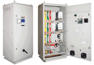
Compared to banks with contactors - capacitor banks with thyristor control UKMT have a very high speed of switching because since there is no need in a delay of actuation for capacitor discharge time.
UKMT - adjustable power high-speed capacitor banks is designed for load power factor correction in a wide range of power consumption.
UKMT application is most popular in networks with a quick-changing load: stamping equipment, welding equipment, lifting and carrying mechanisms, pumps and compressors with varying productivity, etc.
Key point of capacitor banks with thyristor switches operation is based on the fact that commutation operations happen in the moment of voltage passing through zero, i.e. when voltages of capacitor and network are equal. Thanks to this, peak current surges are absent at the capacitors in the switching moment and capacitors life period become longer.
Due to the absence of moving mechanical contacts the thyristor switches have a big resource and are almost noiseless during operation. Thyristor capacitor banks have quick-operating fuses which protect thyristors from current overloads. Also there is thyristors protection from overvoltage in a network.
|
Type designation
|
Quantity and
power of steps
|
Overall dimensions, mm
|
Weight,
kg
|
Normative
document
|
||
|
length
|
width
|
height
|
||||
|
UKMT-0,4-50-12,5 U3.1
|
2?12,5+25
|
800
|
640
|
1700
|
195
|
СТ 1474-1917-
АО-4-035-2012 |
|
UKMT-0,4-62,5-12,5 U3.1
|
12,5+2?25
|
|||||
|
UKMT-0,4-75-12,5 U3.1
|
12,5+25+37,5
|
|||||
|
UKMT-0,4-75-25 U3.1
|
25+50
|
|||||
|
UKMT-0,4-87,5-12,5 U3.1
|
12,5+25+50
|
|||||
|
UKMT-0,4-100-25 U3.1
|
2?25+50
|
|||||
|
UKMT-0,4-125-25 U3.1
|
25+2?50
|
200
|
||||
|
UKMT-0,4-150-25 U3.1
|
25+50+75
|
|||||
|
UKMT-0,4-150-50 U3.1
|
50+100
|
|||||
|
UKMT-0,4-175-25 U3.1
|
25+50+100
|
|||||
|
UKMT-0,4-200-25 U3.1
|
2?25+50+100
|
2000
|
240
|
|||
|
UKMT-0,4-200-50 U3.1
|
2?25+100
|
200
|
||||
|
UKMT-0,4-225-25 U3.1
|
25+2?50+100
|
240
|
||||
|
UKMT-0,4-250-25 U3.1
|
25+50+75+100
|
|||||
|
UKMT-0,4-250-50 U3.1
|
50+2?100
|
205
|
||||
|
UKMT-0,4-275-25 U3.1
|
25+50+2?100
|
245
|
||||
|
UKMT-0,4-300-25 U3.1
|
2?25+50+2?100
|
1600
|
1700
|
350
|
||
|
UKMT-0,4-300-50 U3.1
|
2?50+2?100
|
800
|
2000
|
250
|
||
|
UKMT-0,4-325-25 U3.1
|
25+2?50+2?100
|
1600
|
1700
|
370
|
||
|
UKMT-0,4-350-25 U3.1
|
25+50+75+2?100
|
375
|
||||
|
UKMT-0,4-350-50 U3.1
|
50+3?100
|
255
|
||||
|
UKMT-0,4-400-25 U3.1
|
2?25+50+3?100
|
400
|
||||
|
UKMT-0,4-400-50 U3.1
|
2?50+3?100
|
380
|
||||
|
UKMT-0,4-450-25 U3.1
|
25+50+75+3?100
|
400
|
||||
|
UKMT-0,4-450-50 U3.1
|
50+4?100
|
390
|
||||
|
UKMT-0,4-500-25 U3.1
|
2?25+50+4?100
|
2000
|
455
|
|||
|
UKMT-0,4-500-50 U3.1
|
2?50+4?100
|
1700
|
400
|
|||
|
UKMT-0,4-550-25 U3.1
|
25+50+75+4?100
|
2000
|
||||
|
UKMT-0,4-550-50 U3.1
|
50+5?100
|
1700
|
405
|
|||
|
UKMT-0,4-600-25 U3.1
|
2?25+50+5?100
|
2000
|
470
|
|||
|
UKMT-0,4-600-50 U3.1
|
2?50+5?100
|
460
|
||||
|
UKMT-0,4-650-25 U3.1
|
25+50+75+5?100
|
475
|
||||
|
UKMT-0,4-650-50 U3.1
|
50+6?100
|
460
|
||||
|
UKMT-0,4-675-25 U3.1
|
25+50+6?100
|
480
|
||||
|
UKMT-0,4-700-50 U3.1
|
2?50+6?100
|
490
|
||||
|
UKMT-0,4-750-50 U3.1
|
50+7?100
|
495
|
||||
In bank designation: first number after type – rated voltage in kV,
the second – rated power in kVAr;
the third – power of control step.
Banks are completed with KPC capacitors.
Banks have a protection level IP 21.

