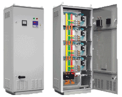
The presence of capacitors in electric power supply networks with nonlinear loads can provoke a occurrence of resonance phenomenon and as a consequence a current increase and capacitors overheating.
In order to avoid resonance modes occurrence it is necessary to use the banks presenting an in-series resonance contour formed by a throttle which is switched on in-series with the capacitors. Such banks are called mismatched filters of higher harmonics. The purpose of such connection is to reduce a network resonance frequency up to the value below the lowest higher harmonic. Throttle power is expressed in a percentage from the capacitor's power. Most frequently the throttles of 5.67%, 7% and 14% are used. Each value of the throttle power has its own resonance frequency. For instance, for 7% mismatching a resonance frequency is 189 Hz. It means that for all harmonics the frequency of which lies above 189 Hz, a network is an inductive resistance and for them the occurrence of resonance mode is unlikely. Therefore there is a solution of the problem for expensive equipment repairing which failed in the result of higher harmonic currents impact.
In order to avoid resonance modes occurrence it is necessary to use the banks presenting an in-series resonance contour formed by a throttle which is switched on in-series with the capacitors. Such banks are called mismatched filters of higher harmonics. The purpose of such connection is to reduce a network resonance frequency up to the value below the lowest higher harmonic. Throttle power is expressed in a percentage from the capacitor's power. Most frequently the throttles of 5.67%, 7% and 14% are used. Each value of the throttle power has its own resonance frequency. For instance, for 7% mismatching a resonance frequency is 189 Hz. It means that for all harmonics the frequency of which lies above 189 Hz, a network is an inductive resistance and for them the occurrence of resonance mode is unlikely. Therefore there is a solution of the problem for expensive equipment repairing which failed in the result of higher harmonic currents impact.
For automatic reactive power compensation of consumers' loads in general-purpose networks with voltage of 0.4 kV and 50 Hz when using the electrical load with nonlinear volt-ampere characteristic, where the harmonics are generated.
Low-voltage filter capacitor banks, adjustable
|
Type designation
|
Quantity and
power of steps
|
Overall dimensions, mm
|
Weight,
not more, kg
|
Normative
document
|
||
|
length
|
width
|
height
|
||||
|
UKMF1(2,3)-0,4-50-12,5 U3
|
2?12,5+25
|
800
|
600
|
1550
|
150(150,165)
|
СТ2347-1917-01-
TOO-4-056-2016 |
|
UKMF1(2,3)-0,4-62,5-12,5 U3
|
12,5+2?25
|
160(170,175)
|
||||
|
UKMF1(2,3)-0,4-75-12,5 U3
|
2?12,5+2?25
|
165(170,185)
|
||||
|
UKMF1(2,3)-0,4-75-25 U3
|
25+50
|
165(165,185)
|
||||
|
UKMF1(2,3)-0,4-87,5-12,5 U3
|
12,5+25+50
|
175(170,195)
|
||||
|
UKMF1(2,3)-0,4-100-12,5 U3
|
2?12,5+25+50
|
180(180,205)
|
||||
|
UKMF1(2,3)-0,4-100-25 U3
|
2?25+50
|
|||||
|
UKMF1(2,3)-0,4-125-25 U3
|
25+2?50
|
1700
|
230(235,250)
|
|||
|
UKMF1(2,3)-0,4-150-25 U3
|
25+50+75
|
250(225,270)
|
||||
|
UKMF1(2,3)-0,4-150-50 U3
|
3?50
|
250(250,270)
|
||||
|
UKMF1(2,3)-0,4-175-25 U3
|
2?25+50+75
|
260(250,285)
|
||||
|
UKMF1(2,3)-0,4-200-25 U3
|
25+2?50+75
|
2000
|
335(340,370)
|
|||
|
UKMF1(2,3)-0,4-200-50 U3
|
4?50
|
345(320,375)
|
||||
|
UKMF1(2,3)-0,4-225-25 U3
|
25+50+2?75
|
345(360,390)
|
||||
|
UKMF1(2,3)-0,4-250-25 U3
|
2?25+50+2?75
|
365(360,405)
|
||||
|
UKMF1(2,3)-0,4-250-50 U3
|
2?50+2?75
|
|||||
|
UKMF1(2,3)-0,4-275-25 U3
|
2?25+3?75
|
380(380,420)
|
||||
In banks designation: the first number – numeral designation of resonance frequency (1-210 Hz for detuning 5,67 %; 2-189 Hz for detuning 7%; 3-135 Гц for detuning 14%);
second - rated voltage in kV;
third - rated power in kVAr;
fourth - power of control step.
second - rated voltage in kV;
third - rated power in kVAr;
fourth - power of control step.
Banks are completed with KPC capacitors and protective throttles for higher harmonic filtration. Banks have a protection degree IP21.

