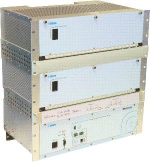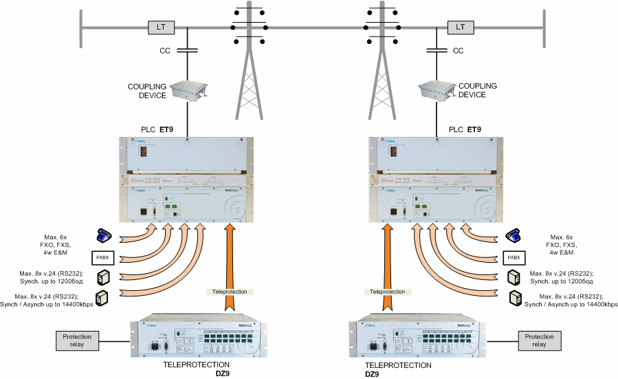
PLC communication links organized over high-voltage transmission lines remains traditional solution in power utilities. PLC links are point to point communications used for signals transmission between substations as well as a part of private communication system of power utilities.
New technologies and solutions in other communication systems are now days used also in PLC systems. Digital signal processing enables transmission of speech, data, SCADA and teleprotection signals inside the same PLC channel.
- transmission of up to 6 PLC channels;
- extended carrier frequency range from 20 kHz up to 1000 kHz – programmable without exchanging hardware;
- high frequency output power (PEP) up to 120 W;
- automatic RF channel equalization;
- service speech channel;
- embedded operation channel for access to management system of remote equipment;
- real time transmission of operational data of remote equipment using pilot channel;
- signaling front panel for basic diagnostic;
- up to 6 universal telephone interfaces (FXO, FXS, 4w E&M);
- up to 8 integrated FSK modems;
- up to 8 integrated QAM modems;
- up to 20 universal audio band interfaces;
- available transit filters on all audio band interfaces;
- dedicated input / output for connecting external teleprotection equipment with speech cut-off and BOOST function;
- integrate or external operation of audio access terminals;
- integrated teleprotection equipment type DZ9;
- pegasus - PC based graphical user interface (GUI) for configuration and management;
- LAN or RS232 port for connecting management PC;
- synchronization with external GPS signal;
- universal power supply – one power supply unit covers complete range of DC an AC voltages;
- optional redundant power supply unit;
- comply with IEC60495.
Applications
- transmission of voice channels (FXO, FXS, 4w E&M);
- transmission of data using FSK (50 – 1200 Bd) or QAM (2400 – 14400 bps) modulation;
- transmission of teleprotection signaling – integrated DZ9 teleprotection equipment or external equipment of other vendors;
- optional external operation of NF9, TG9 access modules - attenuation of connected TK cable up to 26 dB;
- telecommunication resource for different telecommunication equipment in AF band.
Carrier rack options for ET9
| Carrier rack | Description |
|
UCR
|
Carrier rack for external operation of NF9, TG9
|
|
CR-ET9-60
|
Carrier rack for ET9 PLC equipment; up to 6 channels, output power (PEP) up to 60 W |
|
CR-ET9-120
|
Carrier rack for ET9 PLC equipment; up to 6 channels, output power (PEP) up to 120 W |
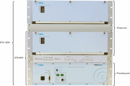
Building blocks for ET9 – power part
| Unit | Description | Number of req. units | |
| ET9-60W | ET9-120W | ||
| PCP | Power part power supply unit | 1 | 2 |
| PTI | Sub rack for power amplifier and transmit line filters | 1 | 2 |
| TPA | Power amplifier | 1 | 2 |
| TXF | Transmit line filter | 1 | 2 |
| RXF | Receive line filter | 1 | 1 |
| IOM | Line matching unit | 1 | 1 |
| SUT | Summing transformer unit | 0 | 1 |
Building blocks for ET9 – processing part
| Unit | Description | Number of req. units | |
|
ET9-60W
|
ET9-120W
|
||
| up to 6 channels | |||
| Min. | Max. | ||
| FPET | Front panel ET9 | 1 | 1 |
| PS | Processing part power supply | 1 | 2 |
| CMS | Centralized management and supervision unit | 1 | 1 |
| HSM | Modulation unit | 1 | 1 |
| NF9 | AF access unit with universal telephone interface; - two 4-w universal AF access interface; - one 2-w or 4-w telephone interface. |
1* | 6 |
| TG9 | AF access unit with integrated modems; - two 4-w universal AF access interface; - two FSK (50 – 1200 Bd) or QAM (2400 – 14400 bps) modems. |
1* | 4 |
| AFA | AF access unit; - two 4-w universal AF access interface. |
1* | 6 |
| GENERAL | |
| RF range Number of PLC channels Nominal channel bandwidth Tx / Rx channel polarization Tx / Rx frequency band position in RF band Channel allocation in RF range Receiver sensitivity Nominal output impedance |
from 20 kHz up to 1000 kHz from 1 up to 6 4 kHz normal / inverse adjacent / non-adjacent programmable in all RF range, step 1 kHz - 31 dBm asymmetrical 75 Ohm, symmetrical 150 Ohm |
| AF PART | |
| Universal AF interface No. of universal AF interfaces useful bandwidth input / output impedance input / output level adjustment transit filters connection type Universal telephone interface No. of telephone interfaces FXS 2-w subscriber interface impedance input / output level adjustment ring frequency FXO 2-w PAX interface impedance input / output level adjustment ring detector 4-w PAX interface with E&M signaling impedance input / output level adjustment E&M signaling speech low-pass filter cut-off frequency Data transmission modem FSK max. no. of modems transmission speed transmission mode modem QAM max. no. of modems transmission speed transmission mode user interface type External mode of operation for NF8 and TG8 access units – characteristic of line interface max. attenuation of connected TK cable input / output level adjustment AF corrector |
max. 20 from 300 Hz to 3720 Hz 600 Ohm, 300 Ohm or high Z from -20 dBm to +10 dBm / step 0,5 dB programmable band pass FIR filters 4-w, symmetrical, galvanic isolated max. 6 (one in each PLC channel) 600 Ohm, symmetrical from -17 dBm to +4 dBm / step 0,1 dB 16, 20, 25 Hz, programmable 600 Ohm, symmetrical from -20 dBm to +5,5 dBm / step 0,1 dB from 13.5 V at freq. 16, 20, 25 Hz 600 Ohm, symmetrical from -20 dBm to +5,5 dBm / step 0,1 dB type I, II, III, IV and V 2k0, 2k2, 2k4, 3k4 8 50 Bd – 1200 Bd asynchronous 8 2400 bps – 14400 bps synchronous or asynchronous V.24 / RS232 26 dB from -20 dBm to +10 dBm / step 0,5 dB 30 available correction curves |
| MONITORING AND CONTROL | |
| Pegasus - GUI based PC software for supervision and configuration over RS232 or LAN interface | |
| LED indicators on front panel | |
| Relay alarm outputs | |
| Full access to remote equipment over internal communication channel | |
| POWER SUPPLY | |
| Power supply Max. power consumption equipment configuration ET9-60W equipment configuration ET9-120W |
DC (40 V – 264 V ), AC (82 V – 264 V)
280 W |
| MECHANICAL CONSTRUCTION | |
| Equipment configuration ET9-60W; 19” / 8 U ET9-120W; 19” / 12 U |
Dimensions (W x H x D) Weight (kg) 482 mm x 354 mm x 332 mm 14 482 mm x 534 mm x 332 mm 23 |


